Two new Apple patents show that Apple is working on hydrogen fuel cell technology.
Patent number 20110256463 is for a parallel fuel stack architecture. The disclosed embodiments relate to a system that provides a power source. The power source includes a set of fuel cells arranged in a fuel cell stack. The power source also includes a power bus configured to connect the fuel cells in a parallel configuration. The inventors are Steven C. Michalske and Bradley L. Spare.
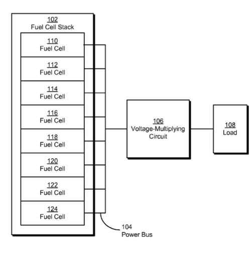
Here’s Apple’s summary of the invention: “The disclosed embodiments relate to a system that provides a power source. The power source includes a set of fuel cells arranged in a fuel cell stack. The power source also includes a power bus configured to connect the fuel cells in a parallel configuration.
“In some embodiments, the power source also includes a voltage-multiplying circuit configured to increase a voltage of the fuel cell stack. In some embodiments, the voltage-multiplying circuit is connected to the power bus. In some embodiments, the voltage-multiplying circuit increases the voltage of the fuel cell stack by a power of two.
“In some embodiments, the fuel cells are arranged in a monopolar configuration that enables sharing of an electrode between two adjacent fuel cells in the fuel cell stack. In some embodiments, each of the fuel cells corresponds to a proton exchange membrane (PEM) fuel cell.”
Patent number 20110256465 is for a reduced-weight fuel cell plate. The disclosed embodiments provide a fuel cell plate. The fuel cell plate includes a substrate of electrically conductive material and a first outer layer of corrosion-resistant material bonded to a first portion of the substrate. To reduce the weight of the fuel cell plate, the electrically conductive material and the corrosion-resistant material are selected to be as light as practicable. Vijay M. Iyer, Jean L. Lee and Gregory Tice are the inventors.
Here’s Apple’s summary of the invention: “The disclosed embodiments provide a fuel cell plate. The fuel cell plate includes a substrate of electrically conductive material and a first outer layer of corrosion-resistant material bonded to a first portion of the substrate. To reduce the weight of the fuel cell plate, both the electrically conductive material and the corrosion-resistant material are selected to be as light as practicable.
“In some embodiments, the fuel cell plate also includes a second outer layer of solderable material bonded to a second portion of the substrate. In some embodiments, the first outer layer and the second outer layer are simultaneously bonded to the substrate using a cladding technique.
“In some embodiments, the fuel cell plate also includes a coating of corrosion-resistant solderable material over the second outer layer. In some embodiments, the second portion of the substrate and the second outer layer correspond to a solder tab for the fuel cell plate.
“In some embodiments, the fuel cell plate also includes a corrosion-resistant sealant applied to an exposed edge of the substrate. In some embodiments, the corrosion-resistant sealant is applied using a welding technique, a molding technique, or a coating technique.
“In some embodiments, the first outer layer is bonded to the first portion of the substrate using a cladding technique, a sputtering technique, a spraying technique, a plating technique, or a coating technique. In some embodiments, the first portion of the substrate and the first outer layer correspond to an electrode for a fuel cell.”
— Dennis Sellers

