An Apple patent (number 20100225429) has appeared at the US Patent & Trademark Office that shows the company is looking at ways and accessories to improve the camera features of the iPhone and iPod touch (and probably the next gen iPad).
Systems and methods are providing for aligning an accessory to an electronic device interface. In particular, some accessories such as optical filters and lens require specific alignment to operative properly. Using a first magnet array positioned around the periphery of the interface and a second magnet array positioned within the accessory, a user can position an accessory on the electronic device and rotate the accessory until the magnets of each array exert a force on an opposing magnet of the other array. By distributing the magnets in a manner that includes no repeating segments, only a single alignment of the accessory relative to the interface can allow the magnet arrays to be properly in opposition. Richard Tsai is the inventor.
Here’s Apple’s background and summary of the invention: “This is directed to systems and methods for coupling and aligning an accessory to an electronic device. In particular, this is directed to systems and methods for coupling accessories requiring a particular alignment to an electronic device interface, such as optical accessories positioned over a lens.
“Electronic devices can include different interfaces by which a user can interact with the device. For example, an electronic device can include one or more input interfaces, such as keys, buttons, or touch screens. In addition, an electronic device can include one or more output interfaces, such a display, audio output circuitry. To further enhance the user’s experience, the electronic device can include one or more sensors operative to detect information regarding the user’s environment, such as an optical or digital camera lens, light sensor, or other sensing mechanism.
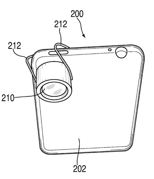
“Because the functionality and features of electronic device interfaces can be limited by space and power restrictions, especially in the context of portable electronic devices, a user may wish to couple one or more accessories to the electronic device. An accessory may cooperate with one or more interfaces to enhance the output or detection of the interface. For example, the electronic device can be coupled to an external lens positioned over an internal camera lens to provide a zoom or filter for captured images. As another example, the electronic device can be coupled to an audio dock operative to receive audio provided by output circuitry of the device (e.g., speakers) and redirect the audio output in a particular direction (with or without audio output circuitry in the accessory electrically coupled to the electronic device). As still another example, the electronic device can be coupled to a directional microphone comprising a structure operative to direct received audio to an internal microphone of the electronic device.
“Some accessories can require specific alignment with a corresponding electronic device interface to operate properly. For example, optical accessories can include gradient filters for which alignment is important. As another example, an accessory plug operative to engage a corresponding opening in the electronic device can include one or more conductive prongs that must be aligned with associated conductive elements of the electronic device. While in some cases, mechanical alignment mechanisms can be used, the mechanical mechanisms can require complex manufacturing processes, increase the number of parts and therefore the risk of failure, and limit the reduction in size of the electronic device.
“This is directed to a magnet array for coupling and aligning an accessory to an electronic device. In particular, this is directed to a pseudo-random magnet array for coupling an accessory requiring a specific alignment to an electronic device.
“To enhance the feature of electronic device interfaces, one or more accessories can be coupled to the electronic device. For example, an optical accessory (e.g., a lens or filter) can be positioned opposite a camera lens of the electronic device. As another example, a directional microphone can be positioned opposite an internal microphone of the electronic device. As still another example, a speaker dock can be positioned adjacent to internal audio output circuitry (e.g., speakers) of the electronic device. Depending on the type of accessory, an electrical connection may or may not be present between the accessory and the electronic device interface. In some embodiments, the accessory may require specific alignment with the electronic device interface to operate properly.
“An accessory can be coupled to the electronic device using any suitable approach. To ensure that the accessory is properly aligned with the device interface, the electronic device can include a series of magnets positioned around the periphery of the interface. The magnets can be disposed such that the polarity of the magnets creates a non-repeating pattern. The accessory device can include a corresponding series of magnets positioned adjacent to the portion of the accessory to be placed in contact with the electronic device such that the polarity of the corresponding magnets is the exact opposite of that of the magnets in the device. Because the pattern can be non-repeating, the magnet arrays of the accessory and the electronic device will be properly aligned for only a single orientation or alignment of the accessory relative to the electronic device. The single orientation can ensure that the accessory is properly aligned when it is coupled to the device.
“In some embodiments, the magnet arrays of the electronic device and of the accessory can be customized to ensure that the accessory is properly coupled to only an authorized electronic device. For example, the electronic device or accessory can include one or more electromagnets for which the polarity can be selected by changing the direction of current flowing through a coil. As another example, the electronic device or accessory can include one or more permanent magnets that the user can flip within the electronic device. Once the user has selected a personalized polarity distribution of the magnet arrays, unauthorized accessories may not align properly with the electronic device, and the accessory may not be usable with other electronic devices.”