An Apple patent (number 20100119634) for a carbon composite mold design has appeared at the US Patent & Trademark Office. The invention relates generally to the formation of carbon composite based components, and, more particularly, to the use of molds to form such carbon composite based components.
A mold assembly or system includes a moldbase that holds mold inserts and has embedded fluid lines to facilitate cooling during part formation. Mold inserts combine to form mold cavities that receive carbon fiber and resin components to form a carbon composite based part. A permanent release coating along a mold component surface that contacts the carbon fiber and resin components facilitates the release of the finished part from the mold component.
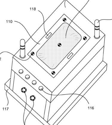
Guide pins and guide pin receiving holes facilitate accurate alignment of mold components. Ejector pins within respective ejector pin shafts help eject a finished part from a respective mold component. An ejector pin shaft cover transfers force from an ejector pin to eject a finished part and also prevents substantial passage of resin into the ejector pin shaft. A fluid actuated ejection system provides fluid based mechanical forces to the ejector pins to facilitate finished part ejection. The inventors are Paul Choiniere, Glenn Aune, John Difonzo, Daniel Hong and Kevin Kenney.
Here’s Apple’s background and summary of the invention: “There are currently a wide number of known ways to form aesthetically pleasing parts and components for items made from various materials across many industries. For example, general part formation can be had by way of machining, casting, stamping, extrusion, cold drawing and injection molding, among numerous other alternatives. Where particularly strong parts or components are desired, another common part formation process can involve composite molding.
“Composite molding generally involves molding a combination of different materials, each having a particular mechanical strength in a different direction, to form a final product that has mechanical strengths in multiple directions. Many popular forms of composite molding involve the use of carbon fibers or another similar component and a resin material, the molded combination of which results in a relatively strong part or component, particularly with respect to the weight of the part. Generally, fibers and resin are placed over or into a mold and are then cured under increased heat and pressure. Fibers typically come in sheet form, which can include “prepreg” or resin impregnated sheets, and are often layered into the mold sheet by sheet. Such a layering process is often performed manually by an operator, as are other steps in a typical composite molding of a part.
“Because resins tend to stick to mold surfaces, removal of a finished part from a mold can be a tricky process that often also involves manual intervention by an operator. Despite the application of a temporary release coating to inner mold surfaces prior to placing in the composite materials, the removal of a finished part from a composite mold still can involve prying and peeling the part away from the inner mold surfaces. Surface defects and blemishes on composite molded parts often occur as a part of the molding and mold removal process, which results in many parts having unique defects or appearances.
“Further, temperature discrepancies from molded part to molded part using traditional composite molding processes can also result in blemishes or defects that are different for each part. Due to these particular examples and other concerns that relate to composite molding, many composite molding processes are highly manual labor intensive by nature, and often result in the formation of parts that are not fully consistent from part to part.
“This is unfortunate in that many manufacturers might desire the mass production of consistent parts that have the strength of carbon composite components. As but one example, it would be particularly helpful if portable electronic device housings and components could be stronger and more durable than what is now typically provided in plastic parts that are formed via ordinary plastic injection molding processes. In particular, it would be beneficial if laptops, notebook computers, and other relatively large and heavy portable computing devices could have outer housings that are better able to protect the entire device from drops and other mechanical shocks.
“Although a material having the toughness of a good carbon composite would be useful, the ability to mass produce laptop housings that are consistent in appearance and performance from such a material would be difficult. Of course, there are a myriad of other examples of parts where it would be desirable to form them from a stronger material such as a carbon composite.
“While many designs and methods of manufacture for providing composite molded parts and components have generally worked well in the past, there is always a desire to provide new and improved designs and processes that result in functional and aesthetically pleasing composite parts that can be mass produced. In particular, it is desirable to provide a carbon composite molding apparatus and process that allows for a more automated mass production of consistent carbon composite parts, such as for computer housings and the like.
“The present invention provides systems and methods that facilitate the mass production of consistent and aesthetically pleasing composite molded parts, such as carbon fiber and resin based composite parts. Such parts can be used for a variety of applications, such as to form outer housings for a laptop computer or other similar device. This can be accomplished by providing a variety of manufacturing techniques and features to traditional composite mold processes, so as to streamline the manufacturing process and to result in the mass manufacture of consistent parts.
“In various embodiments, the invention can include an apparatus adapted to form carbon composite based parts, with the apparatus having a first mold portion including a first mold cavity, a second mold portion adapted to mate with the first mold portion so that composite parts can be formed therebetween, a plurality of ejector pins located within a plurality of respective ejector pin shafts that are formed within one of the mold portions, and an ejector pin shaft stopper fitted within at least one of the plurality of ejector pin shafts.
“The plurality of ejector pins can be adapted to aid in the ejection of a carbon composite based part from one or both of the mold portions, while the ejector pin shaft stopper can be adapted to transfer a mechanical force from a respective ejector pin to the actual carbon composite part for ejection of the part from a respective mold portion. Also, the ejector pin shaft stopper can be further adapted to prevent the substantial passage of any resin component into its respective ejector pin shaft during the formation of the carbon composite based part.
“In various detailed embodiments, a mold assembly for forming carbon composite parts can further include a variety of items. A moldbase can be adapted to hold one or more mold inserts, with the moldbase having one or more internal fluid lines embedded therein to facilitate a fluid based cooling of components during the formation of a carbon composite based part. A plurality of mold inserts, at least one of which is held by the moldbase, can combine to form one or more mold cavities there between while held by the moldbase such that one or more materials including a carbon fiber component and a resin component can be placed therein for the formation of the carbon composite based part.
“At least one of the mold inserts can include a permanent release coating along a surface that contacts the carbon fiber and resin materials to facilitate the release of the carbon composite based part therefrom. One or more guide pins and guide pin receiving holes can be located on at least one of the moldbase and/or plurality of mold inserts, with the one or more guide pins and guide receiving holes being adapted to facilitate the accurate alignment of mold inserts with each other for the formation of the carbon composite based part. Again, a plurality of ejector pins located within a plurality of respective ejector pin shafts having an ejector pin shaft stopper fitted therewithin can be used.
“Also, a fluid actuated ejection system adapted to provide fluid based mechanical forces to the plurality of ejector pins to facilitate the ejection of the carbon composite based part from a respective mold insert can be incorporated into the system. In some embodiments, the fluid actuated ejection system can operate using a gas to provide gas based mechanical forces to the ejector pins.
“In various embodiments, a removable film can be positioned proximate to the permanent release coating, wherein the removable film is adapted to facilitate the release of a carbon composite based part from its respective mold insert, and wherein the removable film can be readily removed from both its respective mold insert and the carbon composite based part. Such a removable film can also serve as an ejector pin shaft cover or stopper by covering the top of one or more of the ejector pin shafts during the formation of a carbon composite based part. In some embodiments, the removable film can be used in addition to or in lieu of the ejector pin shaft stoppers placed within the ejector pin shafts. In some embodiments, the removable film has a thickness of about 10 to 20 microns.
“In various embodiments, the permanent release coating or layer can be formed from nickel-teflon, titantium-nitride, an amorphous carbon/diamond like material, chrome or chrome alloy, or NEDOX. The permanent release coating can have a thickness of about 1 to 5 microns, although other suitable thicknesses may also be used. The permanent release coating or layer can be situated on one mold insert or component or multiple mold components.”
