An Apple patent (number 7916089) for antenna isolation for portable devices has appeared at the US Patent & Trademark Office. It shows that Apple is far from finished with antenna implementations in future iPhones.
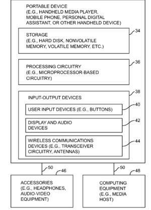
Per the patent portable electronic devices are provided with wireless circuitry that includes antennas and antenna isolation elements. The antennas may include antennas that have multiple arms and that are configured to handle communications in multiple frequency bands. The antennas may also include one or more antennas that are configured to handle communications in a single frequency band. The antennas may be coupled to different radio-frequency transceivers.
For example, there may be first, second, and third antennas and first and second transceivers. The first and third antennas may be coupled to the first transceiver and the second antenna may be coupled to the second transceiver. The antenna isolation elements may be interposed between the antennas and may serve to reduce radio-frequency interference between the antennas. There may be a first antenna isolation element between the first and second antennas and a second antenna isolation element between the second and third antennas. The inventors are Robert W. Schlub and Robert J. Hill.
Here’s Apple’s background and summary of the invention: “This invention relates generally to wireless communications circuitry, and more particularly, to wireless communications circuitry with antenna isolation for electronic devices such as portable electronic devices.
“Handheld electronic devices and other portable electronic devices are becoming increasingly popular. Examples of handheld devices include handheld computers, cellular telephones, media players, and hybrid devices that include the functionality of multiple devices of this type. Popular portable electronic devices that are somewhat larger than traditional handheld electronic devices include laptop computers and tablet computers.
“Due in part to their mobile nature, portable electronic devices are often provided with wireless communications capabilities. For example, handheld electronic devices may use long-range wireless communications to communicate with wireless base stations. Cellular telephones and other devices with cellular capabilities may communicate using cellular telephone bands at 850 MHz, 900 MHz, 1800 MHz, and 1900 MHz.
“Portable electronic devices may also use short-range wireless communications links. For example, portable electronic devices may communicate using the Wi-Fi® (IEEE 802.11) band at 2.4 GHz and the Bluetooth band at 2.4 GHz. Communications are also possible in data service bands such as the 3G data communications band at 2170 MHz band (commonly referred to as UMTS or Universal Mobile Telecommunications System band).
“To satisfy consumer demand for small form factor wireless devices, manufacturers are continually striving to reduce the size of components that are used in these devices. For example, manufacturers have made attempts to miniaturize the antennas used in handheld electronic devices.
“A typical antenna may be fabricated by patterning a metal layer on a circuit board substrate or may be formed from a sheet of thin metal using a foil stamping process. Antennas such as planar inverted-F antennas (PIFAs) and antennas based on L-shaped resonating elements can be fabricated in this way. Antennas such as PIFA antennas and antennas with L-shaped resonating elements can be used in handheld devices.
“Although modern portable electronic devices often use multiple antennas, it is challenging to produce successful antenna arrangements in which multiple antennas operate in close proximity to each other without experiencing undesirable interference. It would therefore be desirable to be able to provide improved antenna structures for wireless electronic devices.
“A portable electronic device such as a handheld electronic device is provided with wireless communications circuitry that includes antennas and antenna isolation elements. The antenna isolation elements may be interposed between respective antennas to reduce radio-frequency interference between the antennas and thereby improve antenna isolation.
“With one suitable arrangement, there are at least three antennas in the wireless communications circuitry. The three antennas may each have a respective antenna resonating element. The antenna resonating elements may be formed from conductive structures such as traces on a flex circuit or stamped metal foil structures (as examples). Each antenna resonating element may have at least one antenna resonating element arm. The arms may be aligned along a common axis.
“The antenna isolation elements may be formed from antenna isolation resonating elements such as L-shaped strips of conductor. The L-shaped conductive strips may have arms that are aligned with the common axis.
“The antennas and the antenna isolation elements may share a common ground plane. With this type of configuration, a first antenna resonating element and the ground plane form a first antenna, a second antenna resonating element and the ground plane form a second antenna, a third antenna resonating element and a ground plane form a third antenna, a first antenna isolation resonating element and the ground plane form a first antenna isolation element, and a second antenna isolation resonating element and the ground plane form a second antenna isolation element.
“If desired, some of the antennas and resonating elements may have multiple arms. For example, the first and third antenna resonating elements may have arms that are aligned with the common axis and arms that are perpendicular to the common axis.
“The first and third antennas may be used to implement an antenna diversity scheme. With one suitable arrangement, a Wi-Fi transceiver that operates at 2.4 GHz and 5.1 GHz is coupled to the first and third antennas, whereas a Bluetooth transceiver that operates at 2.4 GHz is coupled to the second antenna. Antenna isolation elements that operate at 2.4 GHz may be placed between the first and second antennas and between the second and third antennas, thereby isolating the first antenna from the third antenna at 2.4 GHz and isolating the first and third antennas from the second antenna at 2.4 GHz.”
— Dennis Sellers