

An upcoming iPhone could place the antenna behind the Apple logo, based on a new patent (number 20100321253) for a dielectric window antenna for electronic devices at the US Patent & Trademark Office.
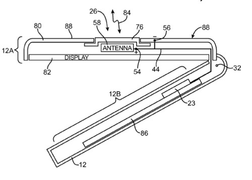
Per the patent, logo antennas are provided for electronic devices such as portable computers. An electronic device may have a housing with conductive housing walls. A logo antenna may be formed from an antenna resonating element such as a patch antenna resonating element, a monopole antenna resonating element, or other antenna resonating element structure. A conductive cavity may be placed behind the antenna resonating element.
A dielectric antenna window that serves as a logo may be used to cover the antenna resonating element. The dielectric antenna window may be mounted in an opening in the conductive housing walls. A positive antenna feed terminal may be coupled to the antenna resonating element. A ground antenna feed terminal may be coupled to the cavity and portions of the conductive housing walls. The dielectric antenna window may be shaped in the form of a logo. The inventors of the patent are Enrique Ayala Vazquez, Gregory A. Springer, Bing Chiang, Douglas B. Kough, Robert W. Schlub, Yi Jiang, Rodney Andres Gomzez Angulo and Ruben Caballero.
Here’s Apple’s background and summary of the invention: “Electronic devices such as portable computers and handheld electronic devices are becoming increasingly popular. Devices such as these are often provided with wireless communications capabilities. For example, electronic devices may use long-range wireless communications circuitry such as cellular telephone circuitry to communicate using cellular telephone bands at 850 MHz, 900 MHz, 1800 MHz, and 1900 MHz (e.g., the main Global System for Mobile Communications or GSM cellular telephone bands).
“Long-range wireless communications circuitry may also be used handle the 2100 MHz band and other bands. Electronic devices may use short-range wireless communications links to handle communications with nearby equipment. For example, electronic devices may communicate using the WiFi (IEEE 802.11) bands at 2.4 GHz and 5 GHz (sometimes referred to as local area network bands) and the Bluetooth® band at 2.4 GHz.
“It can be difficult to incorporate antennas successfully into an electronic device. Some electronic devices are manufactured with small form factors, so space for antennas is limited. Antenna operation can also be blocked by intervening metal structures. This can make it difficult to implement an antenna in an electronic device that contains conductive display structures, conductive housing walls, or other conductive structures that can potentially block radio-frequency signals. It would therefore be desirable to be able to provide improved antennas for wireless electronic devices.
“Logo antennas are provided for electronic devices. An electronic device such as a portable computer or cellular telephone may be provided with a housing. The housing may contain conductive sidewalls. For example, the housing may be formed from a machined block of aluminum or other metals. The walls of the housing may be used to hold conductive components such as displays. Integrated circuits and other electronic components may be mounted within the housing.
“A logo antenna may transmit and receive radio-frequency antenna signals through a dielectric window mounted in a housing wall. The logo antenna may have an antenna resonating element structure such as a patch antenna resonating element. The dielectric antenna window may serve as a logo. The dielectric antenna window may, for example, have the shape of a logo or may contain appropriate text or other visual logo attributes.
“The logo antenna may be provided with a conductive antenna cavity. The cavity may have vertical sidewalls and a planar rear surface or may have other suitable cavity shapes. The antenna resonating element may be interposed between the dielectric antenna window and the antenna cavity. The antenna cavity may help isolate the logo antenna from the electronic components within the housing. With one suitable arrangement, the antenna cavity may be interposed between the antenna resonating element and the display, so that the rear wall of the antenna cavity lies parallel to the exposed planar face of the logo-shaped dielectric antenna window and the display.”
— Dennis Sellers